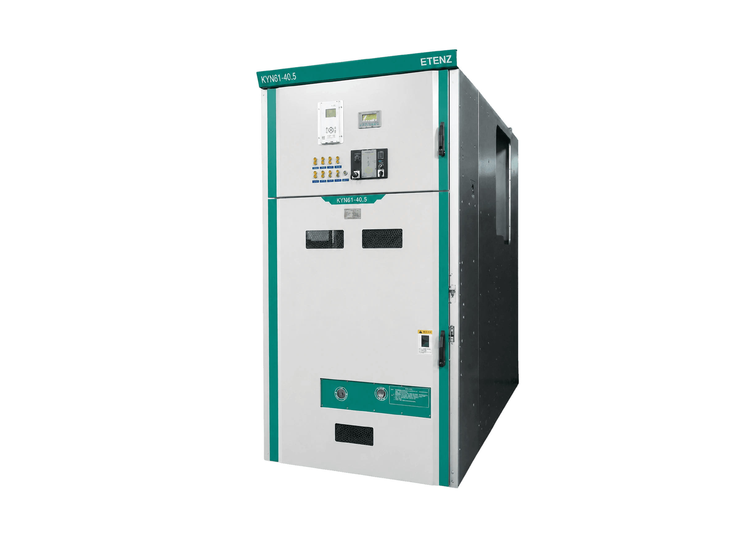
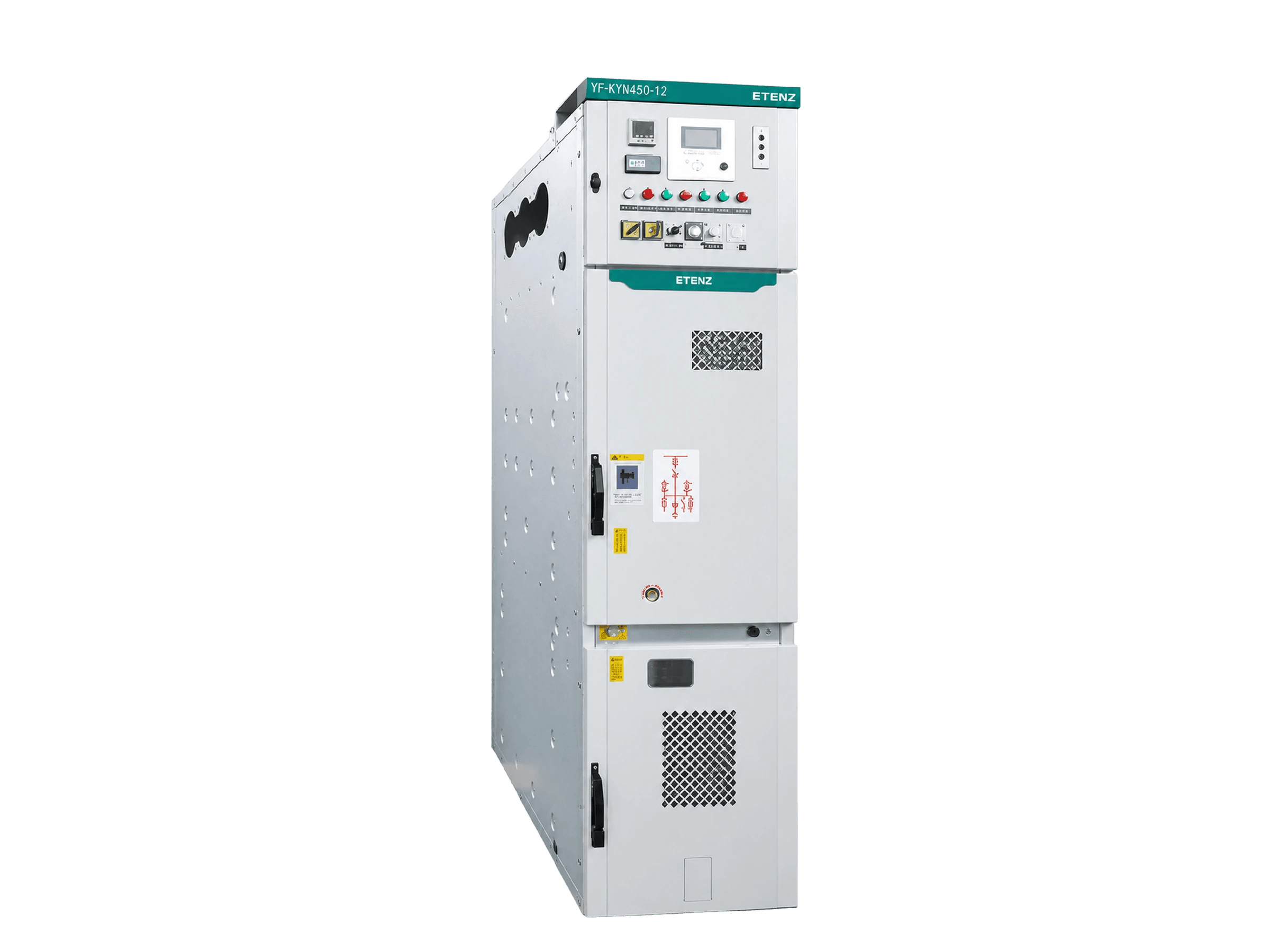
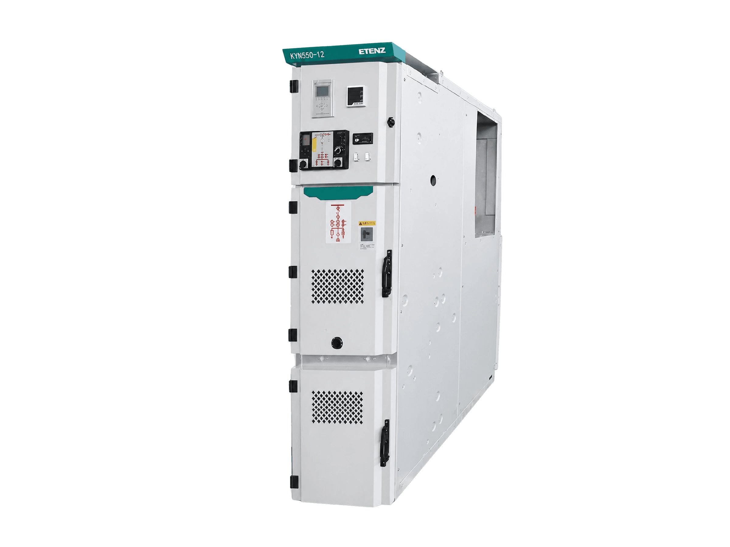
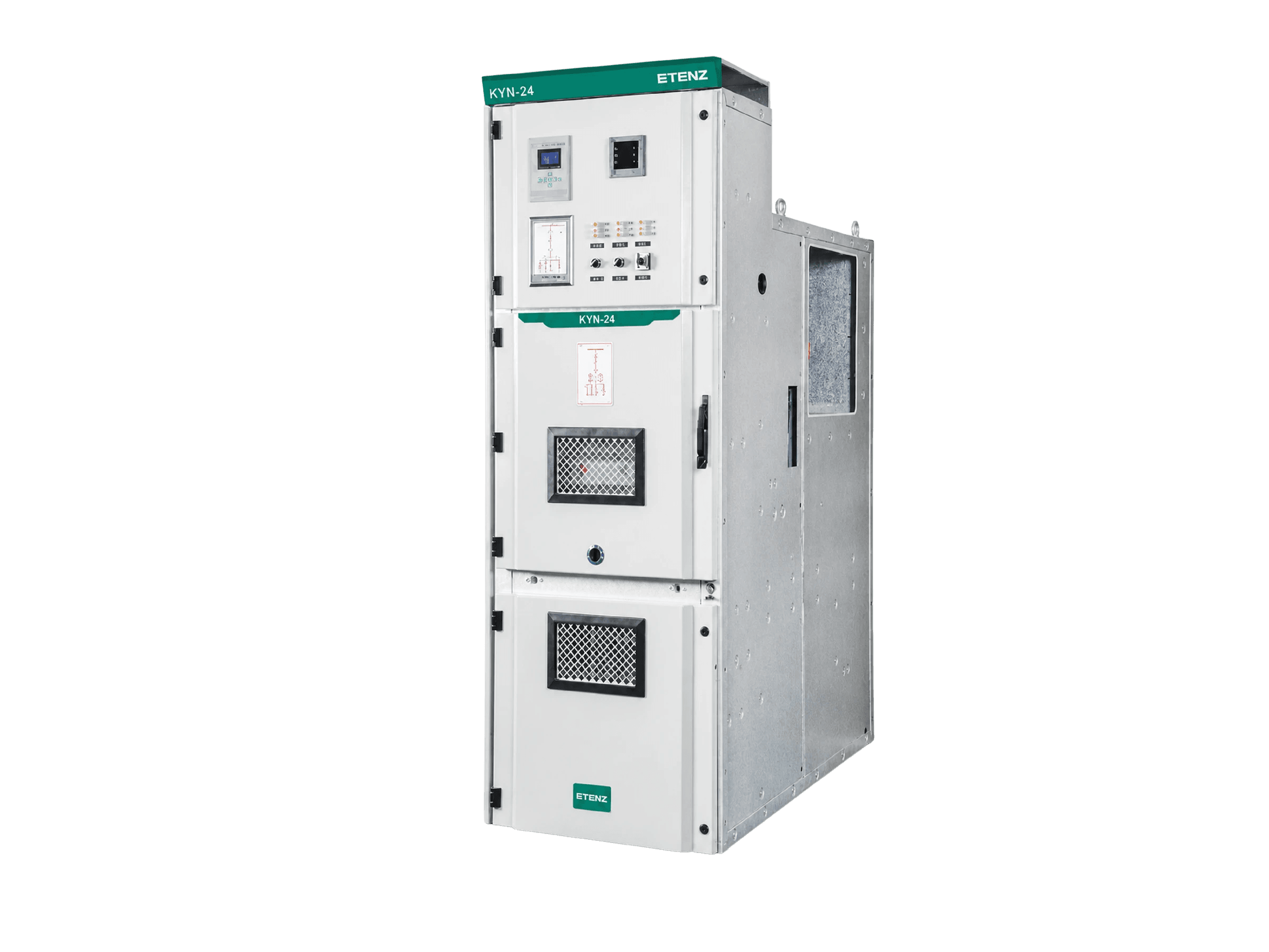
Start from the voltage class. 40.5 kV means KYN61-40.5, 24 kV means KYN□-24, and only at 12 kV and below does the choice open up between KYN28A-12, KYN550-12 and YF-KYN450-12. Among those three, KYN28A-12 carries the widest fault range (16-50 kA) and rated current to 3150 A, which makes it the broadest fit; KYN550-12 takes the main busbar to 4000 A with cubicle widths from 550 to 1000 mm, for high current where width is also constrained; YF-KYN450-12 is the compact type at 475-550 mm wide and 1100 mm deep, for switchrooms short of floor area. The series page carries the full five-model comparison.
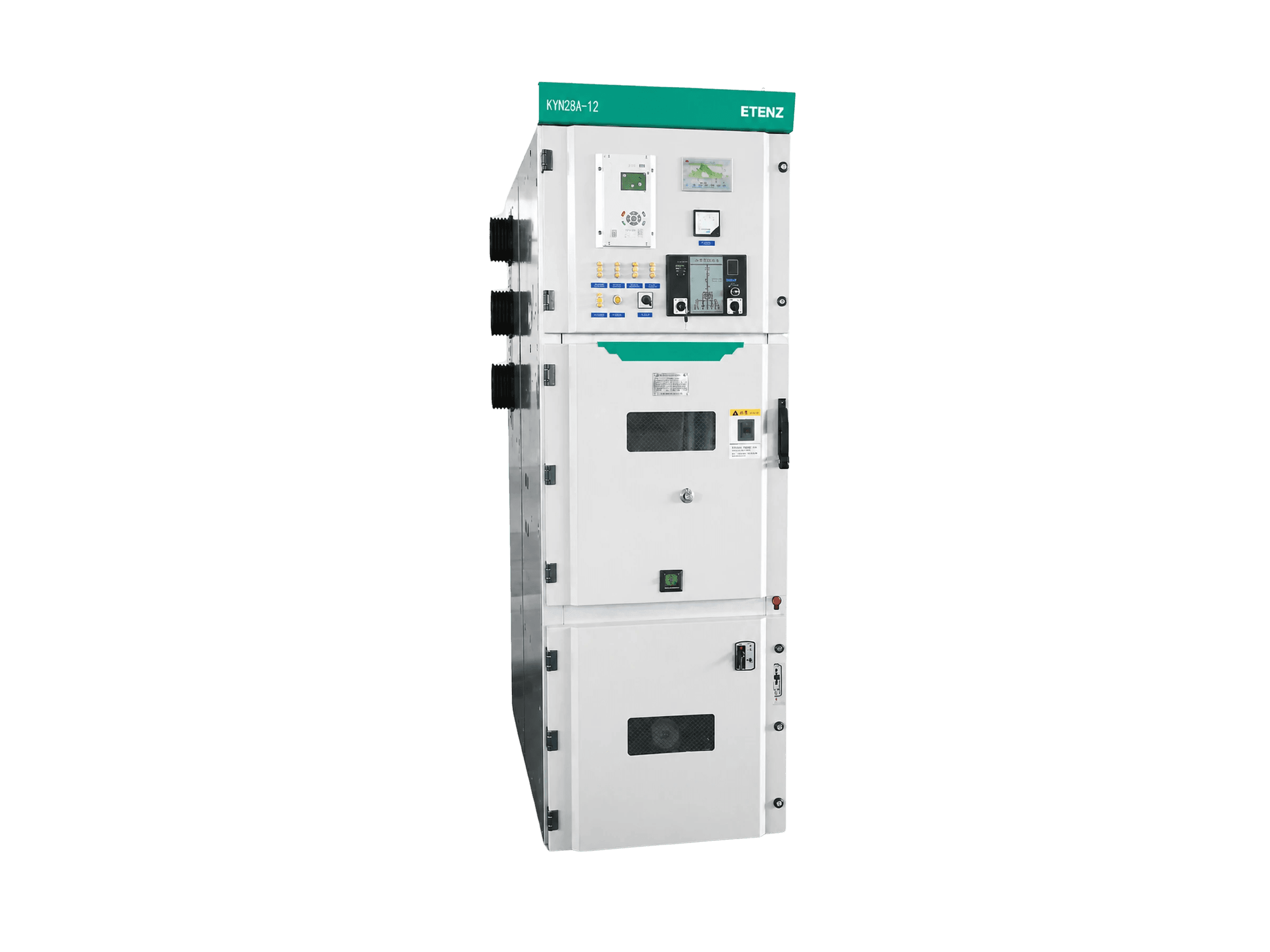
KYN28A-12 Metal-Clad Mid-Mounted Switchgear
For substation and industrial distribution projects: KYN28A-12 is the ETENZ metal-clad mid-mounted switchgear, covering 3.6-12 kV, 630-3150 A rated current and 16-50 kA rated breaking current, supplied as a standard configured assembly or installed as the primary equipment inside an MV switchgear E-House.
Switchgear Room & Distribution RoomPrimary Equipment E-HouseRenewable Grid-Connection Power DistributionCampus Distribution Room
Key Metrics
3.6-12kV
Voltage
630-3150A
Current
16-50kA
Breaking
IP4X
Protection
Product Features

Wide fault range
The ETENZ KYN28A-12 covers 16 to 50 kA rated breaking and 4 s short-time withstand current with 40 to 125 kA peak, so one cubicle type serves a small distribution substation and a high-fault-level main substation alike, without changing type and re-planning the line-up.
Wide fault range
The ETENZ KYN28A-12 covers 16 to 50 kA rated breaking and 4 s short-time withstand current with 40 to 125 kA peak, so one cubicle type serves a small distribution substation and a high-fault-level main substation alike, without changing type and re-planning the line-up.
Wide fault range
The ETENZ KYN28A-12 covers 16 to 50 kA rated breaking and 4 s short-time withstand current with 40 to 125 kA peak, so one cubicle type serves a small distribution substation and a high-fault-level main substation alike, without changing type and re-planning the line-up.

Three voltage tiers
One cubicle type covers 3.6, 7.2 and 12 kV, with the insulation level following the class chosen — 24 / 32 / 42 kV power-frequency withstand and 40 / 60 / 75 kV lightning impulse. Voltage class and insulation level are confirmed as a pair.

Mid-mounted truck
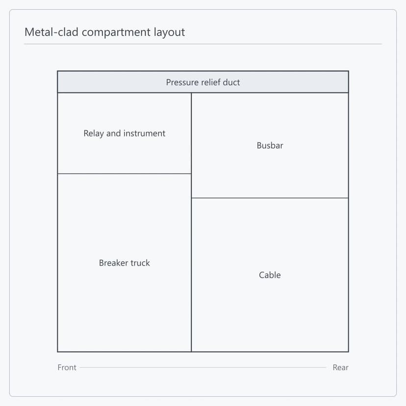
The breaker truck sits in a middle compartment at the front, with the busbar and cable compartments stacked at the rear, so the cubicle is shallower than a front-to-rear arrangement, maintenance is carried out from the front and no rear access aisle is needed — useful where switchroom depth is limited.

E-House ready
A KYN28A-12 line-up can be delivered as the primary equipment inside an MV switchgear E-House or power module. ETENZ develops the line-up layout, busbar connections and internal interfaces together, and the delivery boundary is set once at contract stage.
Product Details
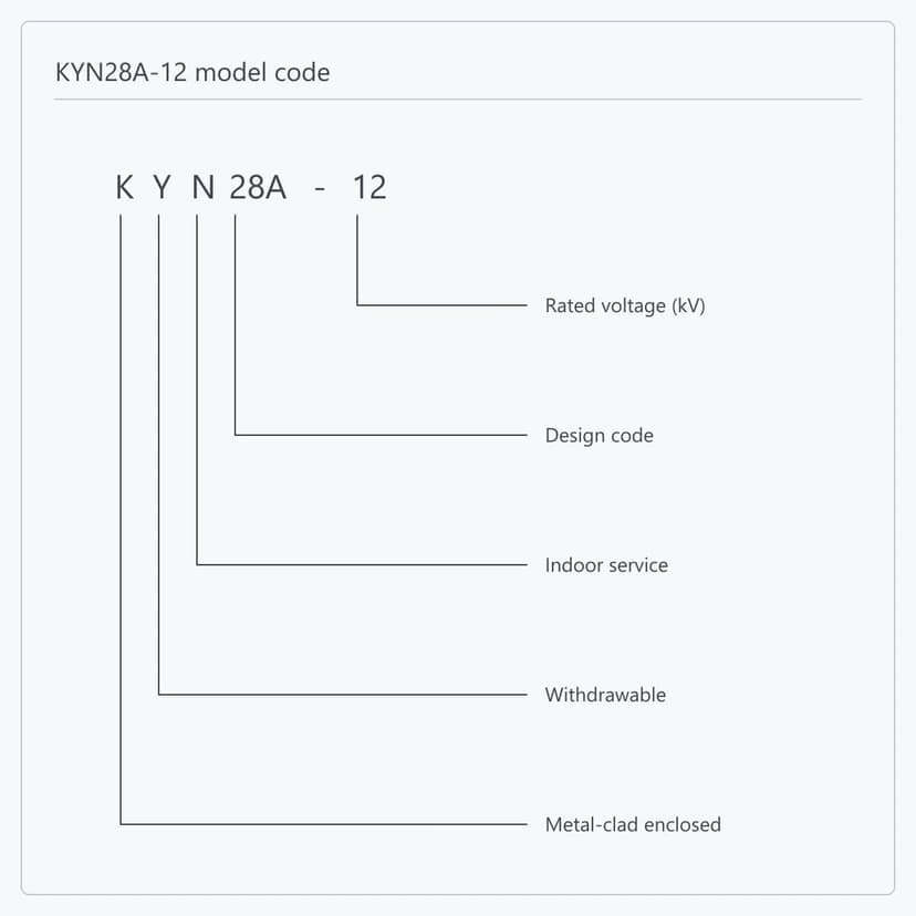
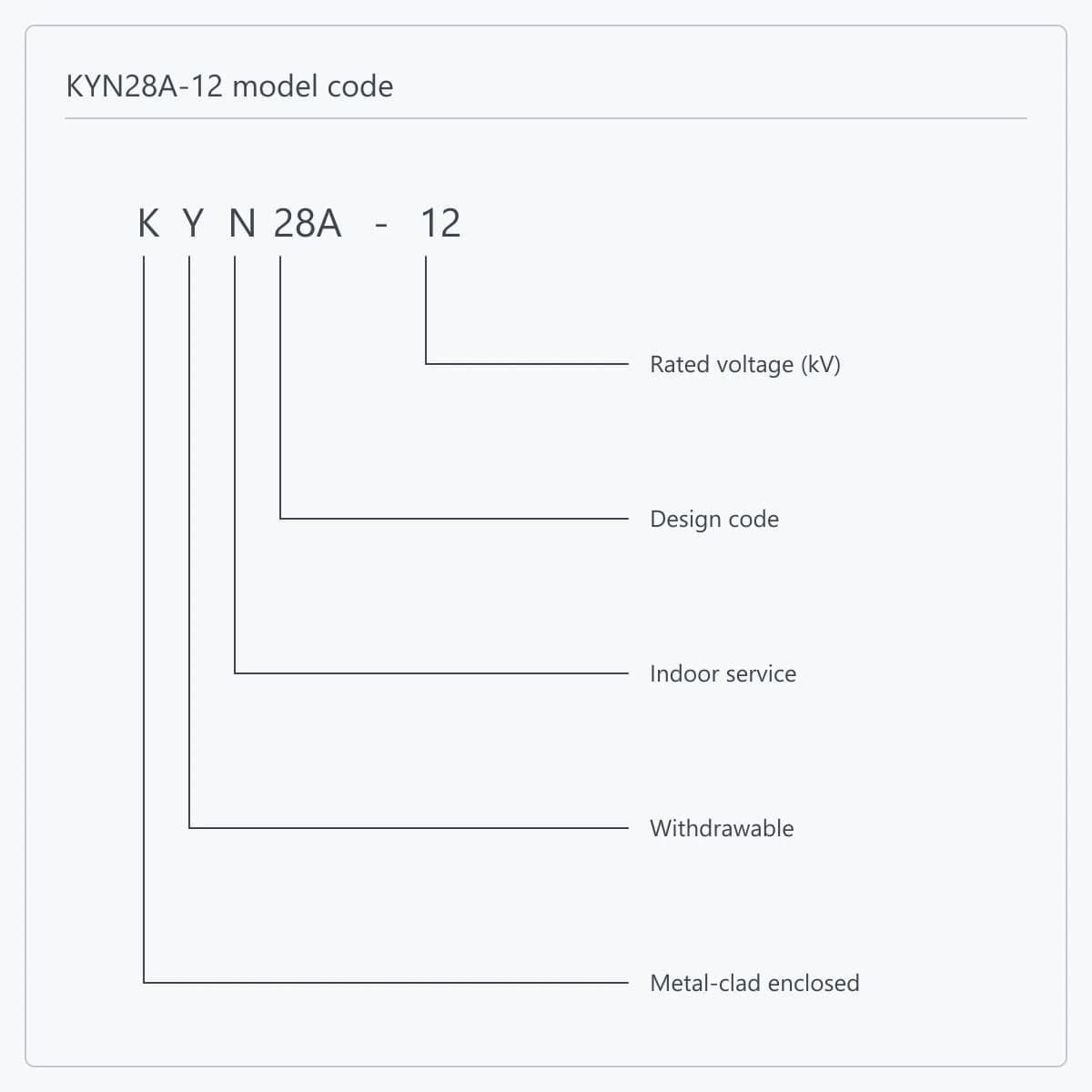
The identity part of KYN28A-12 reads position by position: K is metal-clad enclosed switchgear, Y is the withdrawable pattern, N is indoor service, 28A is the design code and 12 is the voltage class. A complete order designation carries four more positions after it — primary scheme number, operating-mechanism code (D for magnetic, T for spring), rated current and rated breaking current. The first five fix the product identity; the last four fix the configuration of one cubicle, and are what a quotation is confirmed against.
KYN28A-12 is a mid-mounted design: the breaker truck sits in a middle compartment at the front with the relay and instrument compartment above it, while the busbar and cable compartments are stacked at the rear. The four compartments are separated by earthed metal partitions and a pressure relief duct runs along the cubicle roof. The mid-mounted arrangement keeps the cubicle shallower than a front-to-rear layout, maintenance is carried out from the front and no rear access aisle is required, which suits switchrooms with limited depth. Once the truck is withdrawn to the test position, work is confined to the truck compartment while the busbar and cable compartments stay closed. ETENZ develops compartment dimensions, truck travel and maintenance access against the confirmed cubicle type.
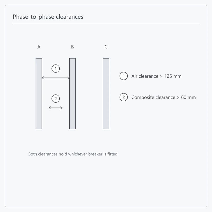
KYN28A-12 states two phase-to-phase clearances, and which one applies depends on the insulation path. Where the path runs wholly through air, the clearance is not less than 125 mm; where part of it runs through solid insulation, the clearance is not less than 60 mm — the smaller figure is permitted because the solid insulation carries part of the duty. Neither figure depends on the main switch: both hold with a ZN63A(VS1) vacuum circuit breaker and with a C3-series fixed load-break switch. The enclosure is aluzinc steel, CNC multi-fold formed and bolted, with powder-coated doors; degree of protection is IP4X, and IP2X between compartments and with the breaker compartment door open. ETENZ checks both clearances cubicle by cubicle at drawing stage against the actual primary scheme.
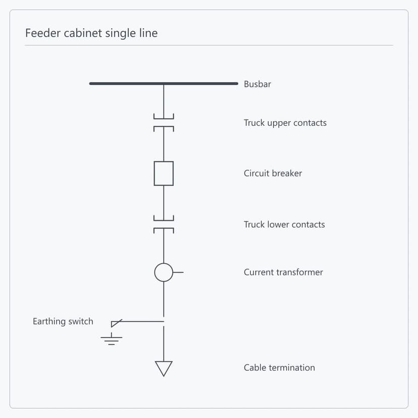
The primary circuit of a KYN28A-12 feeder cubicle runs from the busbar through the upper truck contacts, the circuit breaker, the lower truck contacts, the current transformers and the earthing switch to the cable termination. Incomer, bus-tie, metering and auxiliary-transformer cubicles add or remove devices on that basis. With 630 to 3150 A rated current and 16 to 50 kA breaking capacity, one line-up can hold a large incomer and a small feeder without sectionalising the busbar or derating it. Circuit count, bus-tie and sectionalising arrangement and spare positions are settled at drawing approval, and the line-up length and busbar rating follow from them.
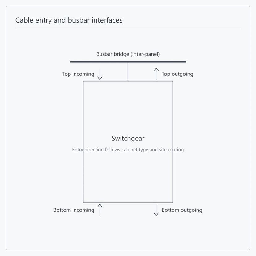
KYN28A-12 accepts top entry with top exit, bottom entry with bottom exit and mixed arrangements; the direction follows the cable termination type and the routing on site. The roof-mounted busbar bridge carries the inter-panel connection, and the busbar section inside each cubicle follows that cubicle rated current — where a line-up mixes ratings, the busbar has to transition continuously between them, which is settled together with the line-up layout at drawing stage. ETENZ fixes cable terminations, busbar connections, inter-panel links and earthing points on the drawings before manufacture, leaving only the connection work on site.
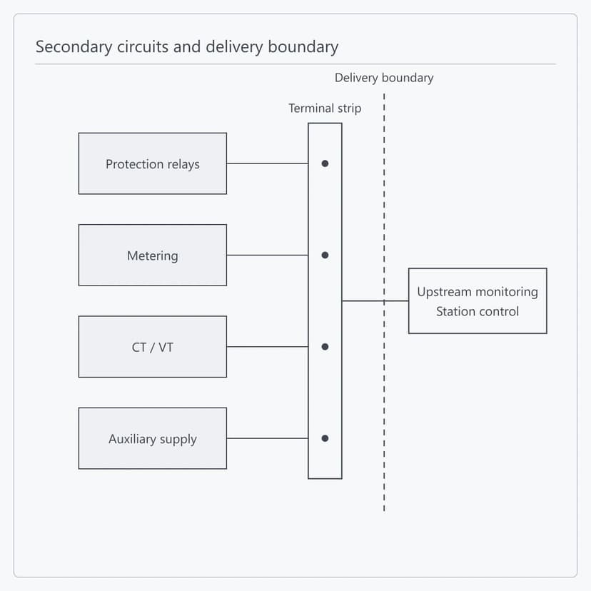
Protection relays, metering devices, CT/VT and auxiliary supplies are installed, wired and checked circuit by circuit in the works, with all secondary signals brought to one terminal strip. A communication interface can be added where remote control and telemetry are required. Everything beyond the terminal strip — the upper-level monitoring system, station control and external I/O — sits on the customer side, with interface type and protocol agreed at technical specification stage. The boundary is confirmed with the project drawings, and connection on site follows them.
Delivery Scope Options
Scope 1
Voltage, insulation and fault level set together
Scope 1Voltage, insulation and fault level set together
Each of the three voltage classes — 3.6, 7.2 and 12 kV — carries its own insulation level; the fault level is chosen from the six steps between 16 and 50 kA against the system fault capacity, and the rated current between 630 and 3150 A follows the circuit duty. The three are settled before manufacture and kept consistent with the nameplate, the drawings and the test records.
Scope Includes:
Voltage class and insulation confirmed as a pair
Fault level set from system fault capacity
Rated current set from circuit duty
Nameplate and drawing consistency check
Scope 1
Voltage, insulation and fault level set together
Scope 1Voltage, insulation and fault level set together
Each of the three voltage classes — 3.6, 7.2 and 12 kV — carries its own insulation level; the fault level is chosen from the six steps between 16 and 50 kA against the system fault capacity, and the rated current between 630 and 3150 A follows the circuit duty. The three are settled before manufacture and kept consistent with the nameplate, the drawings and the test records.
Scope Includes:
Voltage class and insulation confirmed as a pair
Fault level set from system fault capacity
Rated current set from circuit duty
Nameplate and drawing consistency check
Technical Specifications
Product form
Indoor metal-clad mid-mounted switchgear
Model
KYN28A-12
Rated voltage
3.6 / 7.2 / 12
kV
Rated frequency
50
Hz
Breaker rated current
630-3150
A
Switchgear rated current
630-3150
A
Rated breaking current
16 / 20 / 25 / 31.5 / 40 / 50
kA
Short-time withstand current (4 s)
16 / 20 / 25 / 31.5 / 40 / 50
kA
Peak withstand current
40 / 50 / 63 / 80 / 100 / 125
kA
Rated making current (peak)
40 / 50 / 63 / 80 / 100 / 125
kA
1 min power-frequency withstand
24 / 32 / 42, by voltage class
kV
Lightning impulse withstand
40 / 60 / 75, by voltage class
kV
Phase-to-phase air clearance
> 125
mm
Phase-to-phase composite clearance
> 60
mm
Main switch type
ZN63A(VS1) vacuum circuit breaker or C3-series load-break switch
Enclosure material and forming
Aluzinc steel, CNC multi-fold formed and bolted
Degree of protection
IP4X; IP2X between compartments and with the breaker door open
Dimensions (W x D x H)
Confirmed per project
mm
| Parameter | Specification |
|---|---|
| Product form | Indoor metal-clad mid-mounted switchgear |
| Model | KYN28A-12 |
| Rated voltage | 3.6 / 7.2 / 12 kV |
| Rated frequency | 50 Hz |
| Breaker rated current | 630-3150 A |
| Switchgear rated current | 630-3150 A |
| Rated breaking current | 16 / 20 / 25 / 31.5 / 40 / 50 kA |
| Short-time withstand current (4 s) | 16 / 20 / 25 / 31.5 / 40 / 50 kA |
| Peak withstand current | 40 / 50 / 63 / 80 / 100 / 125 kA |
| Rated making current (peak) | 40 / 50 / 63 / 80 / 100 / 125 kA |
| 1 min power-frequency withstand | 24 / 32 / 42, by voltage class kV |
| Lightning impulse withstand | 40 / 60 / 75, by voltage class kV |
| Phase-to-phase air clearance | > 125 mm |
| Phase-to-phase composite clearance | > 60 mm |
| Main switch type | ZN63A(VS1) vacuum circuit breaker or C3-series load-break switch |
| Enclosure material and forming | Aluzinc steel, CNC multi-fold formed and bolted |
| Degree of protection | IP4X; IP2X between compartments and with the breaker door open |
| Dimensions (W x D x H) | Confirmed per project mm |
Product FAQs
They are fixed together. The voltage class follows the nominal system voltage and the insulation level follows from it: 3.6 kV pairs with 24 kV power-frequency withstand and 40 kV lightning impulse; 7.2 kV with 32 kV and 60 kV; 12 kV with 42 kV and 75 kV. The three sets are paired, so a lower-class insulation level cannot be used at a higher voltage. Give the nominal and the highest operating system voltage with the enquiry and the insulation level follows.
The fault level follows the system fault capacity at the point of installation and the rated current follows the circuit load; the two are set independently. Send the system fault capacity or the short-circuit calculation and the level is taken from the six steps of 16, 20, 25, 31.5, 40 and 50 kA at not less than the calculated value, with peak withstand current following at 40, 50, 63, 80, 100 or 125 kA. The rated current is then chosen between 630 and 3150 A against the circuit duty.
A complete order designation is KYN28A-12 followed by four positions: the primary scheme number, which says whether the cubicle is an incomer, a feeder, a bus-tie or a metering cubicle; the operating-mechanism code, D for magnetic and T for spring; the rated current; and the rated breaking current. The first two follow from where the cubicle sits in the system and from the control supply conditions, and the last two are the answers to the two questions above. Send the single-line diagram and the circuit schedule and all four can be set cubicle by cubicle.
The two values correspond to two insulation paths. Where the path runs wholly through air, the phase-to-phase clearance is not less than 125 mm; where part of it runs through solid insulation, the clearance is not less than 60 mm. The smaller figure is permitted because the solid insulation carries part of the duty, and GB 3906 gives the pair for 12 kV. Neither depends on the main switch — both hold with a ZN63A(VS1) vacuum circuit breaker and with a C3-series fixed load-break switch — and both can be checked cubicle by cubicle at drawing stage against the actual primary scheme.
The choice follows the circuit function. Incomer, feeder and bus-tie circuits that have to break fault current take a ZN63A(VS1) vacuum circuit breaker; circuits that only switch load current, with upstream protection coordinated, can take a C3-series fixed load-break switch. Where remote supervision is required, a communication interface is added for remote control and telemetry, with the protocol and point list agreed at technical specification stage. The main switch type also affects the truck and fixed-contact box dimensions, so state it when sending the single-line diagram.
Three items are enough for a preliminary proposal: the single-line diagram, the voltage class with the rated current, and the system fault capacity. For a contract-grade quotation, add the cubicle count with the primary scheme for each, the control supply type and voltage, the metering and protection requirements, the cable entry arrangement and cable sizes, the communication interface, the switchroom dimensions and depth limit, and the standards and document list for the destination market.
Yes. Switchgear is supplied as equipment; an MV switchgear E-House or power module is supplied as an enclosure — the first is the cubicle itself, the second covers the enclosure, the equipment layout, the auxiliary systems and interface integration. Where a KYN28A-12 line-up is delivered as the primary equipment inside an E-House, ETENZ develops the line-up layout, busbar connections and internal interfaces together, and the delivery boundary is set once at contract stage.
Related Solutions
Prefabricated Infrastructure
Prefabricated E-House Project Delivery Solution
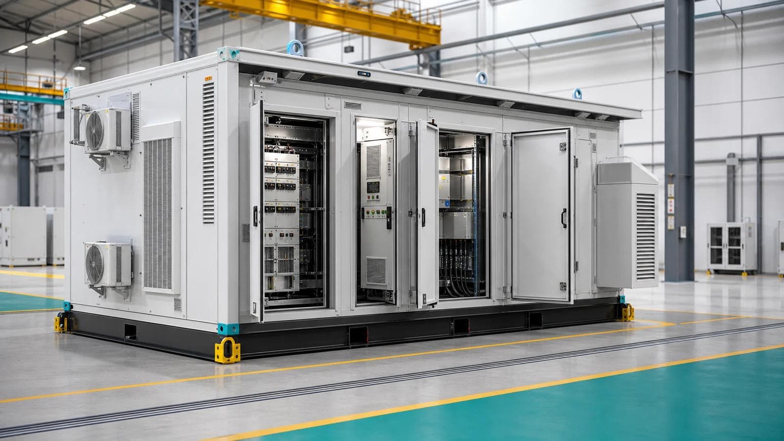
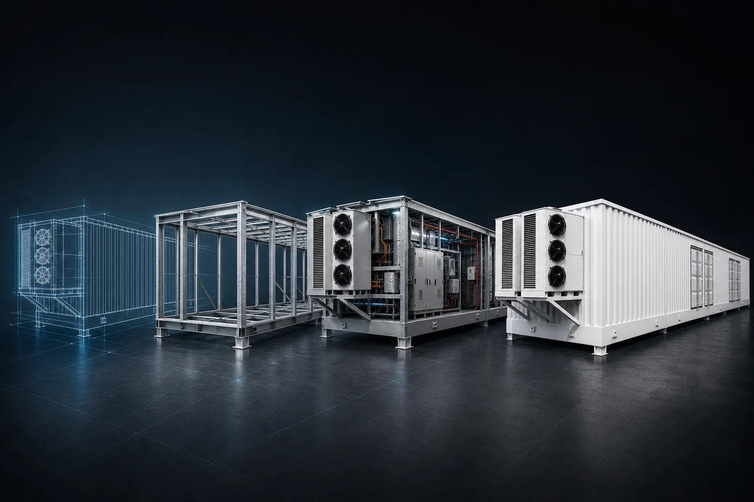
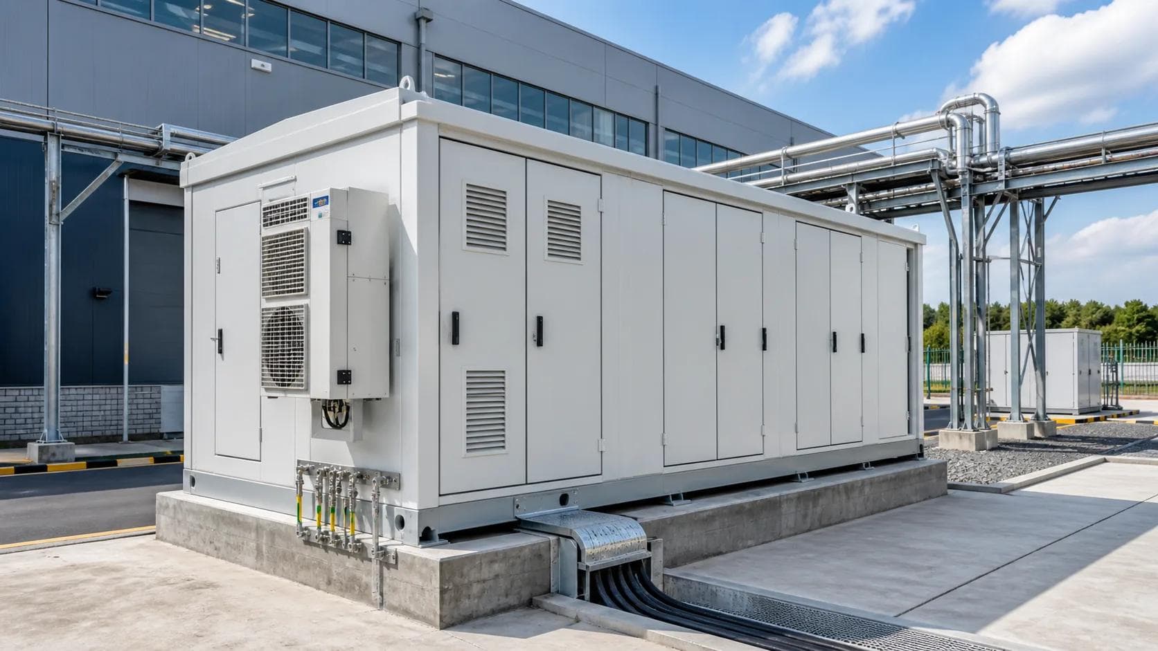
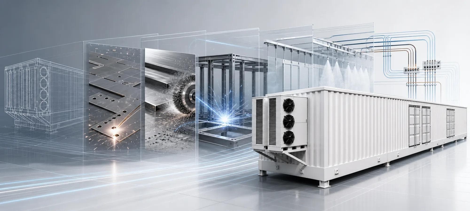
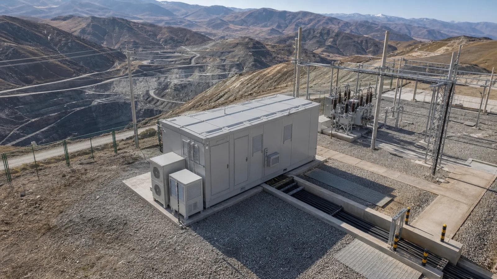
ETENZ delivers configurable prefabricated E-House projects for electrical equipment integration, covering enclosure manufacturing, layout, wiring paths, factory checks, interface coordination, and OEM/ODM cooperation.
Product Application Cases


Related Products
Distribution Switchgear
Withdrawable Metal-Clad MV Switchgear - KYN Series
Electrical E-Houses
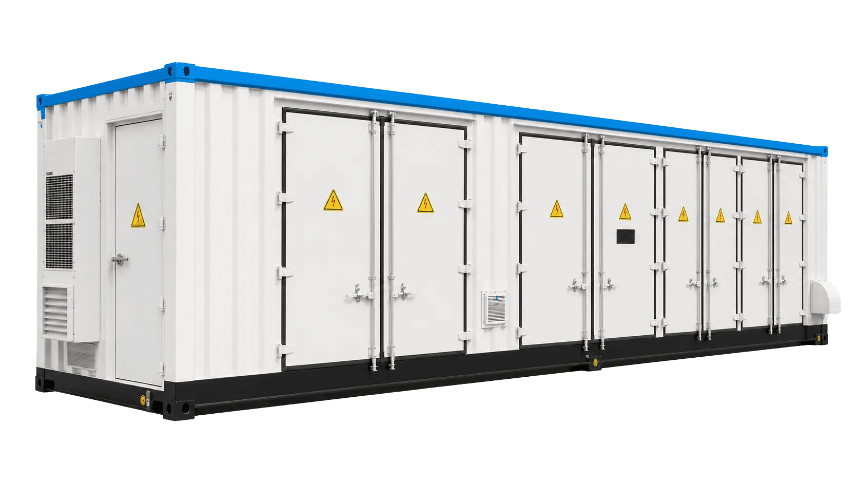
Containerized MV Switchgear E-House
Electrical E-Houses
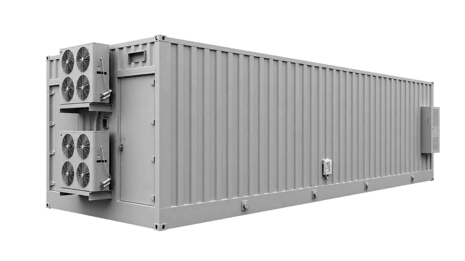
MV Switchgear E-House
Distribution Switchgear
YF-KYN450-12 Compact Withdrawable Switchgear
Distribution Switchgear
KYN550-12 Metal-Clad Switchgear
Distribution Switchgear