That is its most typical use. At 475 to 550 mm wide and 1100 mm deep it is a size down from an ordinary 12 kV cubicle and will often fit an existing switchroom without civil work, while rated breaking to 40 kA meets a system fault capacity raised by an upstream change. Three things are checked first: whether the clear depth takes the 1100 mm cubicle plus front operating space and truck travel, whether the clear height takes the 2200 mm cubicle plus the busbar bridge, and whether the existing cable trench and entry directions line up. Send the site dimensions and the new system fault capacity and feasibility can be judged.
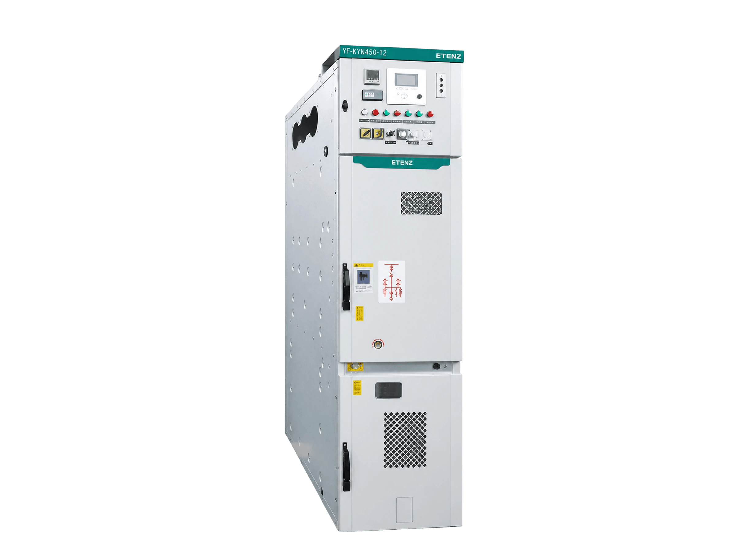
YF-KYN450-12 Compact Withdrawable Switchgear
For switchrooms short of area and for uprating an existing distribution room in place: YF-KYN450-12 is the ETENZ compact withdrawable switchgear rated 12 kV, 630-1600 A rated current and 25-40 kA rated breaking current, at 475-550 mm wide and 1100 mm deep, supplied as a standard configured assembly or installed as the primary equipment inside an MV switchgear E-House.
Switchgear Room & Distribution RoomPrimary Equipment E-HouseRenewable Grid-Connection Power DistributionCampus Distribution Room
Key Metrics
12kV
Voltage
630-1600A
Current
25-40kA
Breaking
475-550mm
Width
Product Features

Smallest footprint
The ETENZ YF-KYN450-12 is 475 to 550 mm wide, 1100 mm deep and 2200 mm high — the smallest envelope in the KYN series. Where switchroom area is tight, or an existing distribution room has to be uprated in place, this is the model to look at first.
Smallest footprint
The ETENZ YF-KYN450-12 is 475 to 550 mm wide, 1100 mm deep and 2200 mm high — the smallest envelope in the KYN series. Where switchroom area is tight, or an existing distribution room has to be uprated in place, this is the model to look at first.
Smallest footprint
The ETENZ YF-KYN450-12 is 475 to 550 mm wide, 1100 mm deep and 2200 mm high — the smallest envelope in the KYN series. Where switchroom area is tight, or an existing distribution room has to be uprated in place, this is the model to look at first.

Small is not derated
Rated breaking current reaches 25, 31.5 and 40 kA with making and dynamic withstand of 63, 80 and 100 kA and a 4 s thermal rating. The cubicle is small but the fault capability is not, so a compact type need not be given up to reach the required fault level.

Spring mechanism
The operating mechanism is spring energy-storage. Manual or motor charging is followed by a single closing stroke, with the charged state and switch position visible from the front, and no external air or hydraulic supply to maintain.

E-House ready
A YF-KYN450-12 line-up can be delivered as the primary equipment inside an MV switchgear E-House or power module. The narrow cubicle and 1100 mm depth fit more bays into a given module length, and the delivery boundary is settled once at contract stage.
Product Details
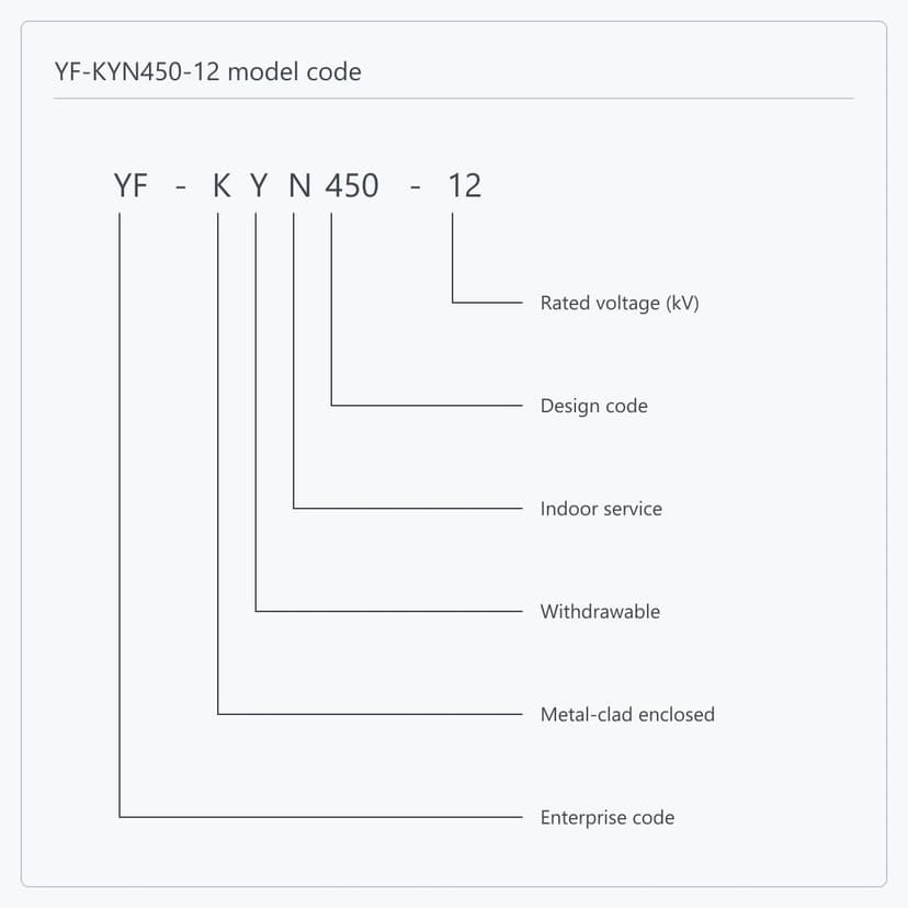
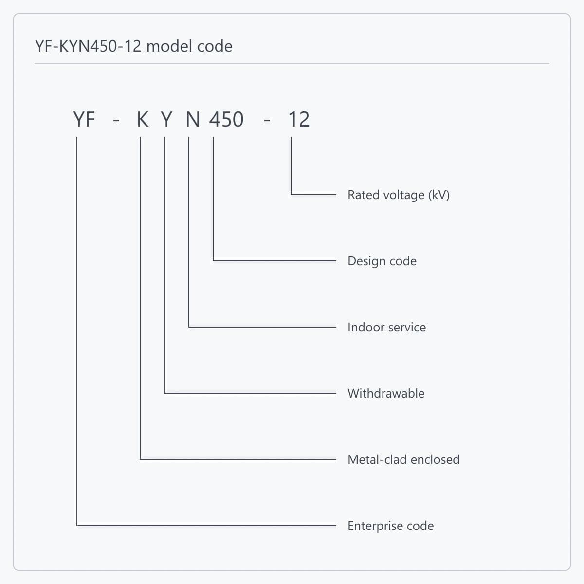
The identity part of YF-KYN450-12 reads position by position: YF is the enterprise code, K is metal-clad enclosed switchgear, Y is the withdrawable pattern, N is indoor, 450 is the design code and 12 is the voltage class. Note the first position — an enterprise code means this is an in-house design series rather than a national-standard type, so selection is checked against the figures on this page rather than against generic data carrying a similar number. Do not confuse it with YF-XGN450-12 either: that one is box-type fixed pattern, on the same 450 platform but a different equipment class, where isolation comes from a disconnector blade rather than from racking a truck out.
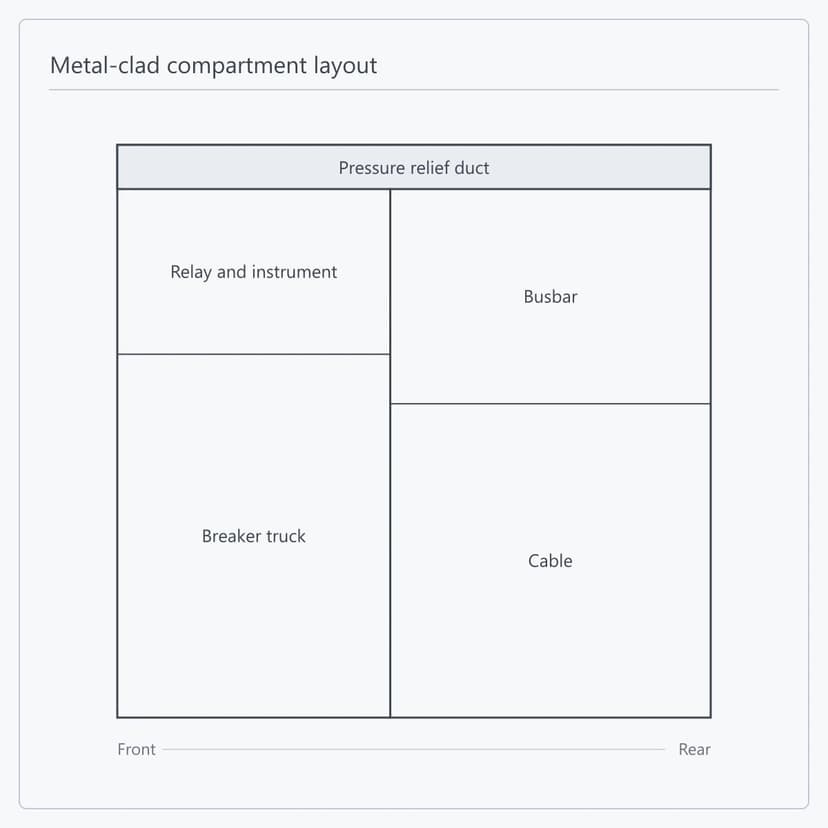
YF-KYN450-12 is divided into truck, busbar, cable and relay-instrument (LV) compartments, and the enclosure of every compartment is earthed on its own; pressure relief devices sit above the truck, busbar and cable compartments. A separate 5 x 40 mm copper earth bar runs inside the cable compartment, continuing into the adjoining cubicles and bonded to the body, for devices that need a direct earth. Enclosure and partitions are aluzinc steel, CNC machined with multiple folds and joined with rivet nuts and high-strength bolts; the doors are powder coated. Heaters are fitted in the breaker and cable compartments against condensation in high humidity or where temperature swings widely.
This model is worth choosing because two things hold at once. The envelope is 475 to 550 mm wide, 1100 mm deep and 2200 mm high, the smallest in the series; and rated breaking current reaches 40 kA, making and dynamic withstand 100 kA, with a 4 s thermal rating — the fault capability is not downgraded to buy the smaller size. The situation where both are needed together is specific: an existing distribution room is being uprated in place, the column spacing and depth cannot move, and the system fault capacity has risen after an upstream change. Moving to a larger cubicle type would mean civil work, while this one can meet the new fault level within the existing space. Rated current comes in three steps — 630, 1250 and 1600 A — chosen against circuit duty and independent of the fault level. ETENZ checks feasibility against the existing switchroom dimensions and the new system data.
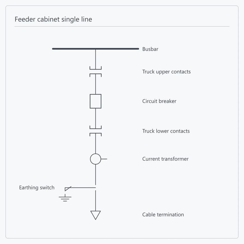
The primary circuit of a YF-KYN450-12 feeder cubicle runs from the busbar through the upper truck contacts, the circuit breaker, the lower truck contacts, the current transformers and the earthing switch to the cable termination. Twelve ready primary schemes are given for this type: bottom incomer, incomer isolation, top incomer, isolated cable top incomer, bottom feeder, top feeder, VT, bus-tie, bus coupler, fixed metering, arc-suppression VT and withdrawable metering, all rated 630 to 1600 A. The scheme decides which devices a cubicle carries and it also decides its envelope — the top-feeder and metering schemes each have their own width. The line-up is set cubicle by cubicle from the scheme list.
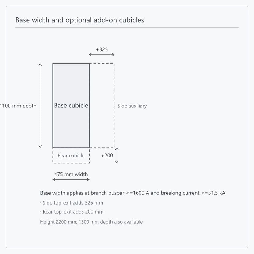
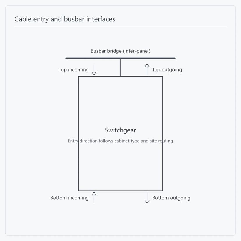
YF-KYN450-12 accepts top entry with top exit, bottom entry with bottom exit and mixed arrangements. On this type the exit direction changes the envelope directly: a side top exit adds a 325 mm auxiliary cubicle at the side, and a rear top exit adds a 200 mm rear cubicle, for which single-core cable is preferred. The roof-mounted busbar bridge carries the inter-panel connection and the busbar section inside each cubicle follows its rated current. ETENZ fixes exit direction, cable terminations, busbar connections and earthing points on the drawings before manufacture, leaving only the connection work on site.
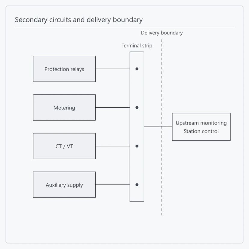
Protection relays, metering devices, CT/VT and auxiliary supplies are installed, wired and checked circuit by circuit in the works, with all secondary signals brought to one terminal strip. Secondary wiring reaches the truck through a plug whose moving half runs in a nylon bellows, the fixed socket sitting at the upper right of the breaker compartment; the plug can only be made or broken with the truck in the test or isolated position, and is locked by a mechanical interlock in the service position. A live-line indication device is fitted, with sensors on the busbar or feeder side and the indicator socket in the LV compartment. Everything beyond the terminal strip — the upper-level monitoring system and external I/O — sits on the customer side, with interface type and protocol agreed at technical specification stage.
Supply Scope and Delivery Boundary
All three apply to every order: what is supplied, how far secondary work goes at the works, and which inspection records and documents ship with the cubicles.
Single Cubicle or Complete Lineup Supply
Cubicles are supplied singly or as a complete lineup against the order schedule. Enclosure, main circuit and internal connections are assembled at the works and shipped as complete cubicles; where transport limits apply, the lineup is split and the joining interface is set beforehand. Where the cubicles are to arrive inside a prefabricated cabin, the E-House line takes on the enclosure, internal arrangement and cubicle fixing, and the switchgear is delivered as equipment housed within it.
This covers:
Single cubicle or complete lineup
Complete-cubicle shipment and split points
Joining and fixing interface
In-cabin delivery handled by the E-House line
Single Cubicle or Complete Lineup Supply
Cubicles are supplied singly or as a complete lineup against the order schedule. Enclosure, main circuit and internal connections are assembled at the works and shipped as complete cubicles; where transport limits apply, the lineup is split and the joining interface is set beforehand. Where the cubicles are to arrive inside a prefabricated cabin, the E-House line takes on the enclosure, internal arrangement and cubicle fixing, and the switchgear is delivered as equipment housed within it.
This covers:
Single cubicle or complete lineup
Complete-cubicle shipment and split points
Joining and fixing interface
In-cabin delivery handled by the E-House line
Technical Specifications
Product form
Indoor metal-clad withdrawable switchgear
Model
YF-KYN450-12
Rated voltage
12
kV
Rated current
630 / 1250 / 1600
A
Rated breaking current
25 / 31.5 / 40
kA
Rated making current
63 / 80 / 100
kA
Dynamic withstand current
63 / 80 / 100
kA
Thermal withstand current
25 / 31.5 / 40
kA
Rated thermal withstand time
4
s
1 min power-frequency withstand
Confirmed per project
kV
Lightning impulse withstand
Confirmed per project
kV
Operating mechanism
Spring energy-storage
Degree of protection
IP4X
Compartments
Truck, busbar, cable and relay-instrument (LV) compartments
Earthing
5 x 40 mm continuous copper earth bar in the cable compartment; each compartment enclosure earthed on its own
Anti-condensation
Heaters in the breaker and cable compartments
Dimensions (W x D x H)
(475-550) x (1100/1300) x 2200
mm
Base width condition
Width 475 mm at branch busbar <=1600 A and breaking current <=31.5 kA
Mass per cubicle
400-500
kg
| Parameter | Specification |
|---|---|
| Product form | Indoor metal-clad withdrawable switchgear |
| Model | YF-KYN450-12 |
| Rated voltage | 12 kV |
| Rated current | 630 / 1250 / 1600 A |
| Rated breaking current | 25 / 31.5 / 40 kA |
| Rated making current | 63 / 80 / 100 kA |
| Dynamic withstand current | 63 / 80 / 100 kA |
| Thermal withstand current | 25 / 31.5 / 40 kA |
| Rated thermal withstand time | 4 s |
| 1 min power-frequency withstand | Confirmed per project kV |
| Lightning impulse withstand | Confirmed per project kV |
| Operating mechanism | Spring energy-storage |
| Degree of protection | IP4X |
| Compartments | Truck, busbar, cable and relay-instrument (LV) compartments |
| Earthing | 5 x 40 mm continuous copper earth bar in the cable compartment; each compartment enclosure earthed on its own |
| Anti-condensation | Heaters in the breaker and cable compartments |
| Dimensions (W x D x H) | (475-550) x (1100/1300) x 2200 mm |
| Base width condition | Width 475 mm at branch busbar <=1600 A and breaking current <=31.5 kA |
| Mass per cubicle | 400-500 kg |
Product FAQs
No. They share the 450 platform and a similar width, but they are different equipment classes. This one is the withdrawable pattern, where the isolating gap is formed by racking the truck out. YF-XGN450-12 is box-type fixed pattern, where a disconnector blade inside the cubicle forms a visible isolating gap. Maintenance therefore differs: a withdrawable unit is racked out and replaced whole, a fixed one is worked on inside the cubicle. The choice follows the operating regime and the cost of an outage, not the dimensions.
475 mm is the base width and it carries a stated condition: branch busbar rated current not above 1600 A and breaking current not above 31.5 kA. Beyond that the width goes to 550 mm. The exit arrangement adds further: a side top exit adds a 325 mm auxiliary cubicle at the side, a rear top exit adds a 200 mm rear cubicle, for which single-core cable is preferred. Metering and arc-suppression VT cubicles have their own widths, between 600 and 800 mm. So the overall line-up length has to be added up from each cubicle actual scheme; multiplying 475 by the cubicle count will not give it.
Four, strung along the operating sequence. Once the truck moves from the service position to the isolated or test position, the shutters cover the fixed-contact boxes to prevent entry into a live compartment, and can be padlocked for maintenance. With the circuit breaker closed, the truck can neither be withdrawn from service nor pushed from isolated or test into service; conversely the truck must be fully locked in the test or the service position before the breaker can be operated. The earthing switch can be operated only with the truck in the isolated or test position or removed from the cubicle, and once it is closed the truck cannot be pushed back into service. With the truck in service the secondary plug is locked and cannot be withdrawn; and until the plug is connected, the breaker on the truck can only be opened, its closing mechanism being held by an electromagnetic lock.
It does not. Rated breaking current is 25, 31.5 and 40 kA, rated making and dynamic withstand 63, 80 and 100 kA, with a 4 s thermal rating — the same tier as ordinary-sized cubicles of the class. The value is chosen from the system fault capacity at the installation point, not inferred from the cubicle size. Send the fault capacity or the short-circuit calculation and the rating is taken as the first step not below it.
The steps are 630, 1250 and 1600 A, chosen against that circuit’s duty and independent of the fault level — the fault level follows the system fault capacity and rated current follows the load, and neither is derived from the other. Where a circuit needs more than 1600 A this model does not apply and a higher-rated member of the series should be used; the series page carries the full five-model comparison.
Four things give a preliminary scheme: the single-line diagram, rated voltage with each circuit’s rated current, the system fault capacity, and the switchroom clear dimensions with height. For a contract-grade quotation, add each cubicle’s primary scheme, control supply type and voltage, metering and protection requirements, cable entry arrangement and cable sizes, communication interfaces, and the standards and document list for the destination market.
Yes. Switchgear is supplied as equipment while an MV switchgear E-House or power module is supplied as an enclosure — the first is the panel itself, the second covers the enclosure, equipment layout, auxiliary systems and interface integration. The narrow cubicle and 1100 mm depth fit more bays into a given module length and allow a narrower module. Where it goes inside as the primary equipment, ETENZ details the line-up arrangement, busbar connections and in-module interfaces, and the delivery boundary is settled once at contract stage.
Related Solutions
Prefabricated Infrastructure
Prefabricated E-House Project Delivery Solution
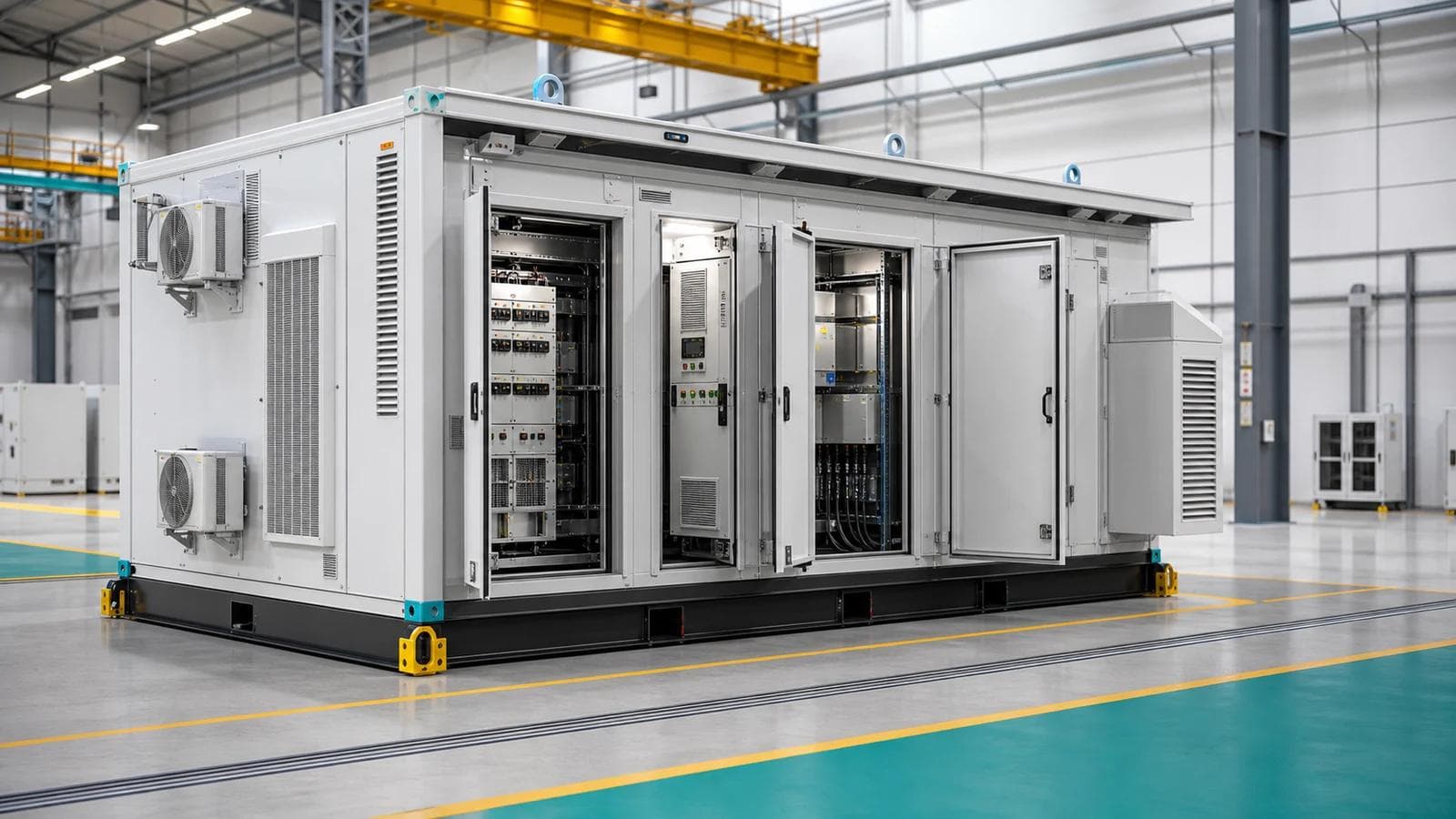
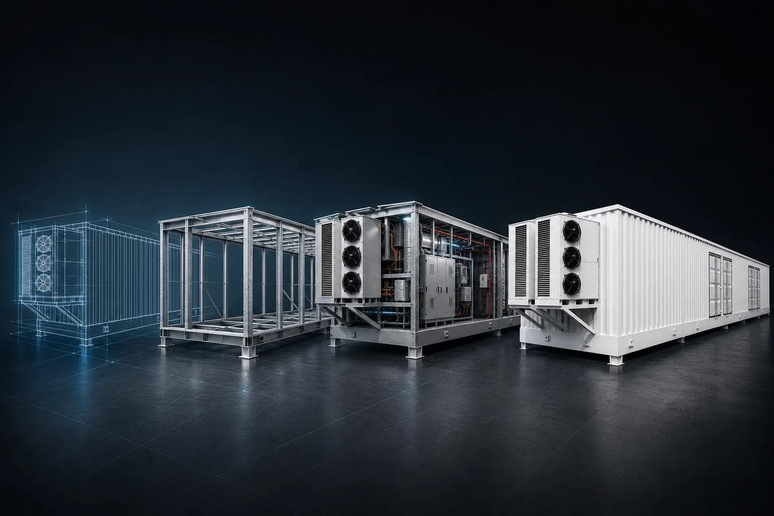
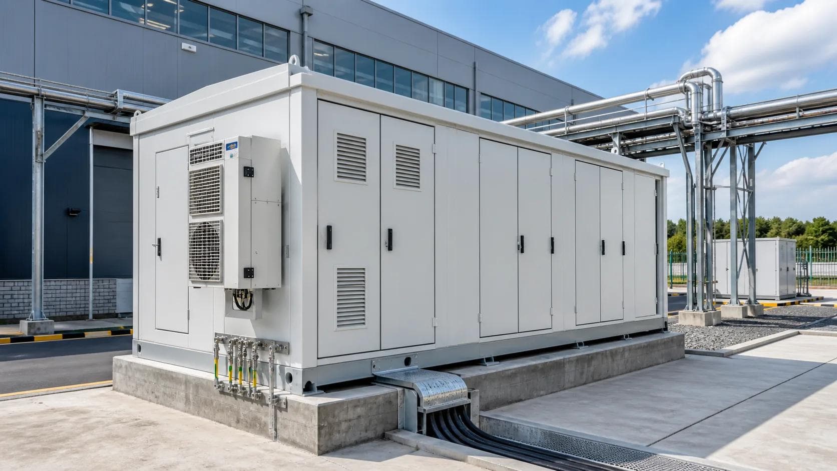
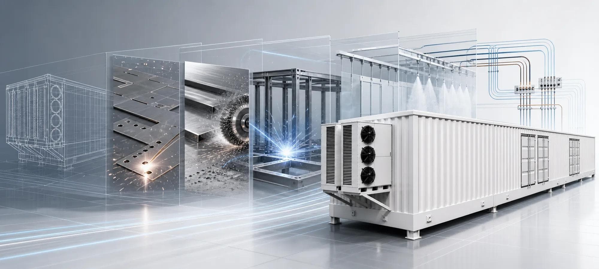
ETENZ delivers configurable prefabricated E-House projects for electrical equipment integration, covering enclosure manufacturing, layout, wiring paths, factory checks, interface coordination, and OEM/ODM cooperation.
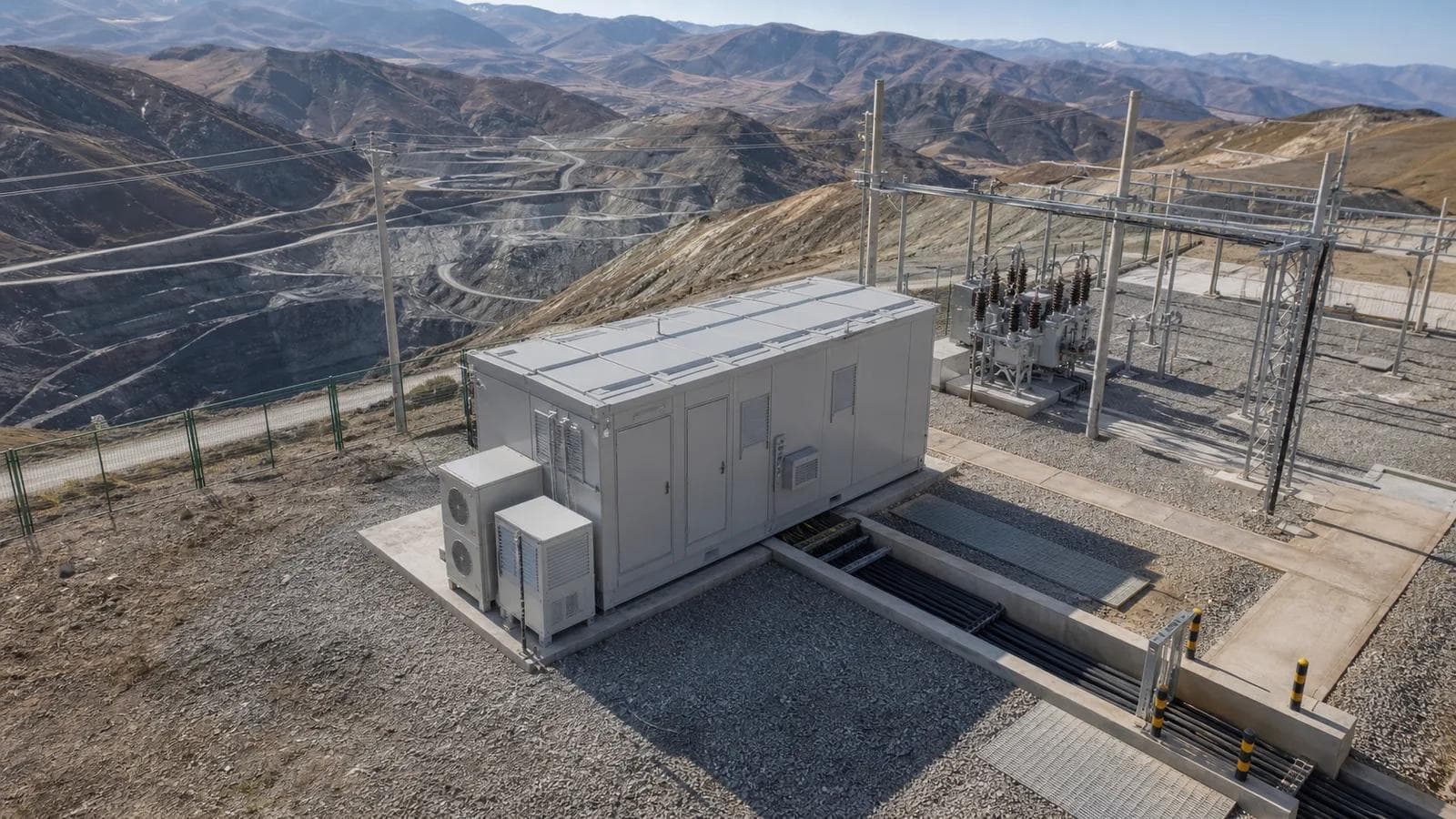
Product Application Cases


Related Products
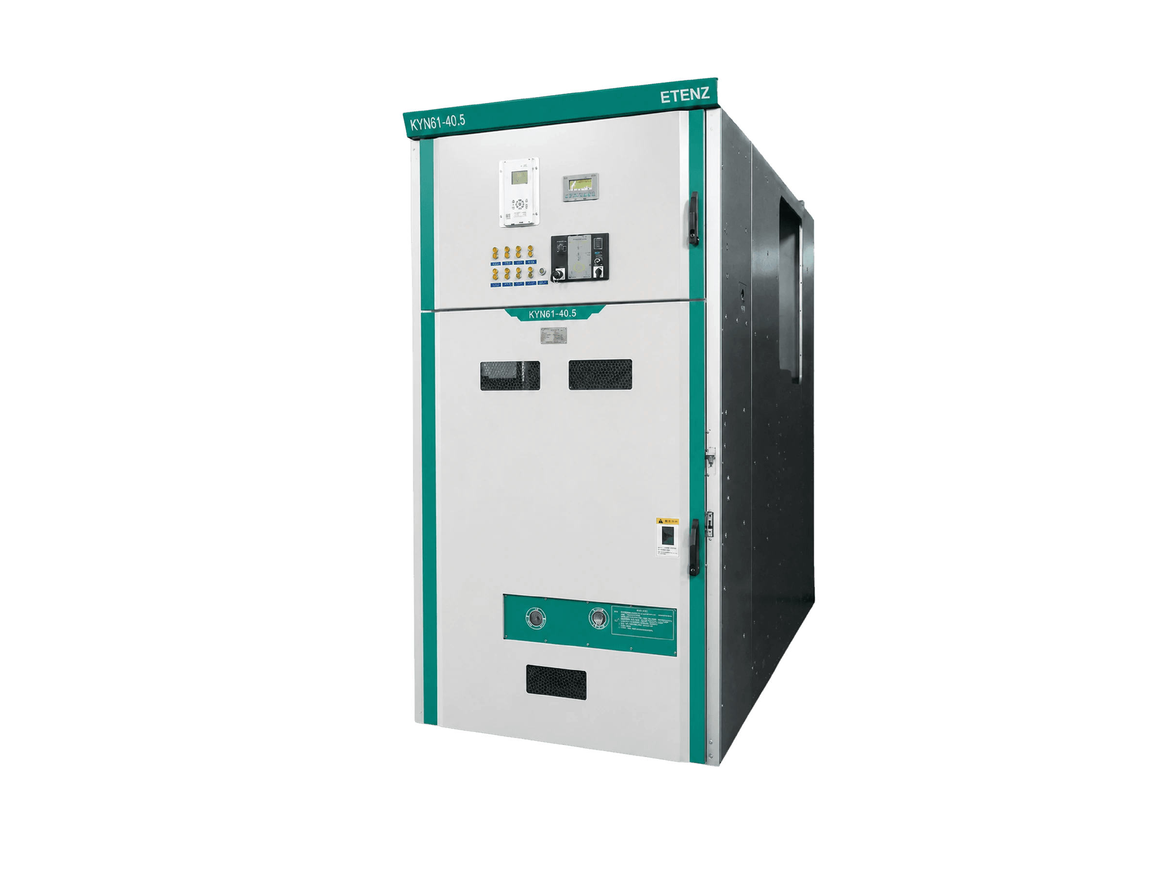
Distribution Switchgear
Withdrawable Metal-Clad MV Switchgear - KYN Series
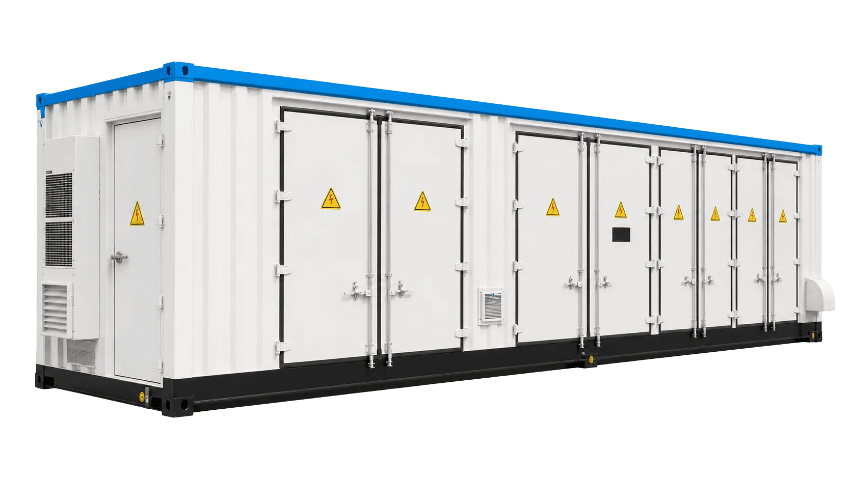
Electrical E-Houses
Containerized MV Switchgear E-House
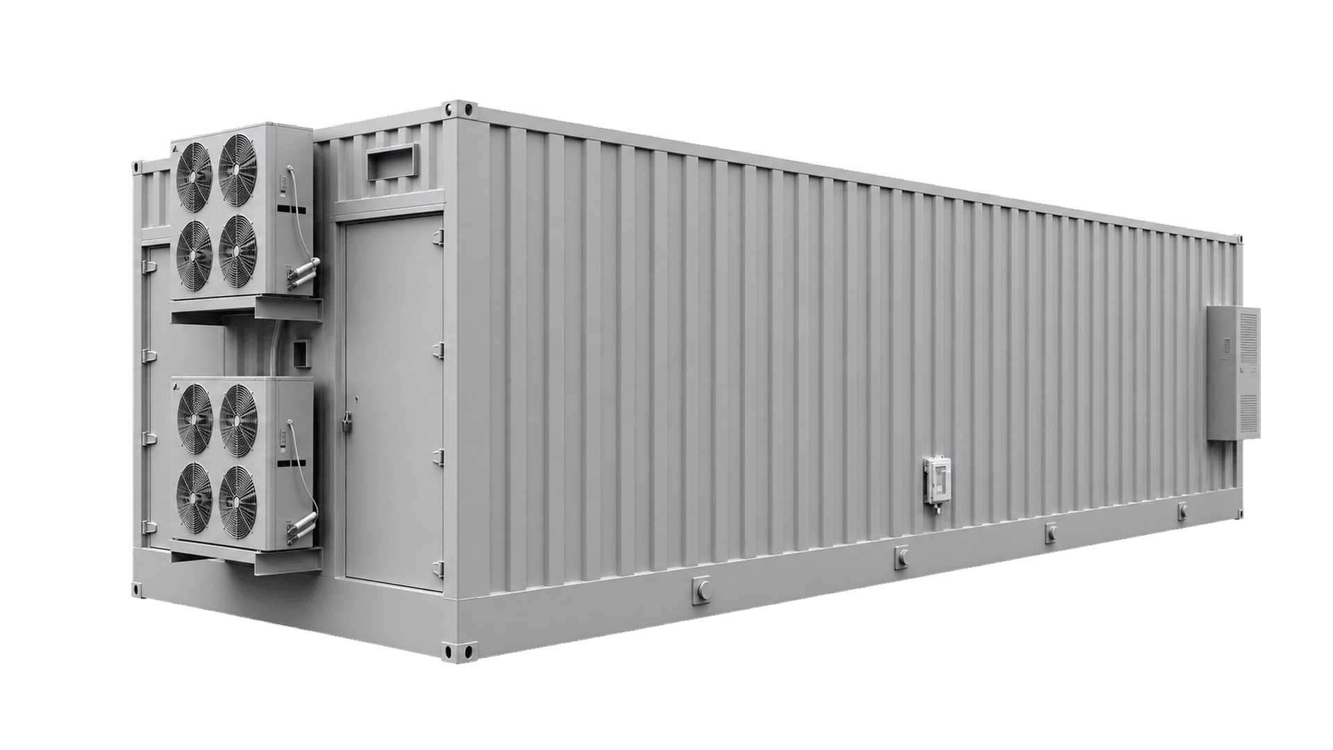
Electrical E-Houses
MV Switchgear E-House
Distribution Switchgear
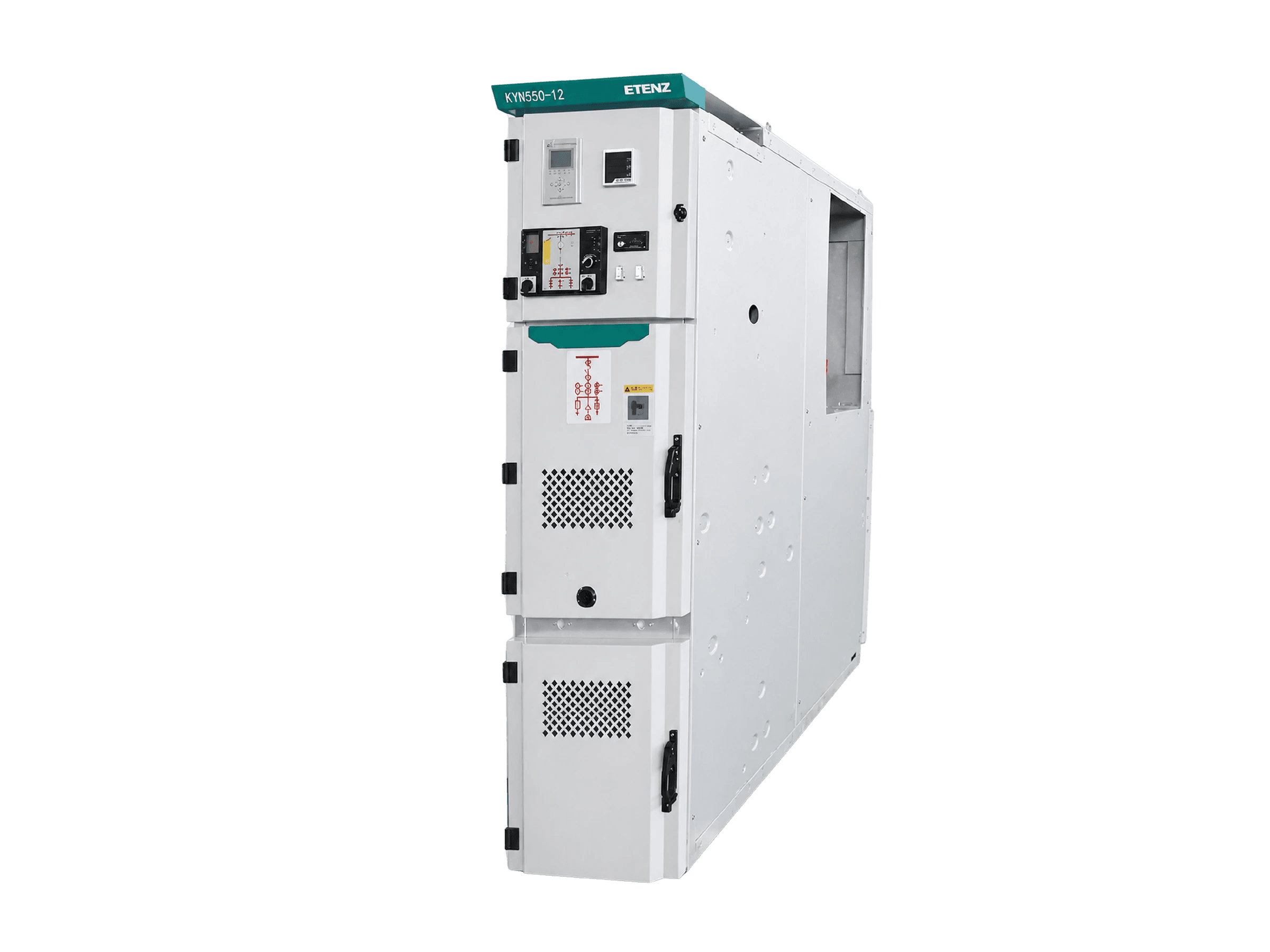
KYN550-12 Metal-Clad Switchgear
Distribution Switchgear
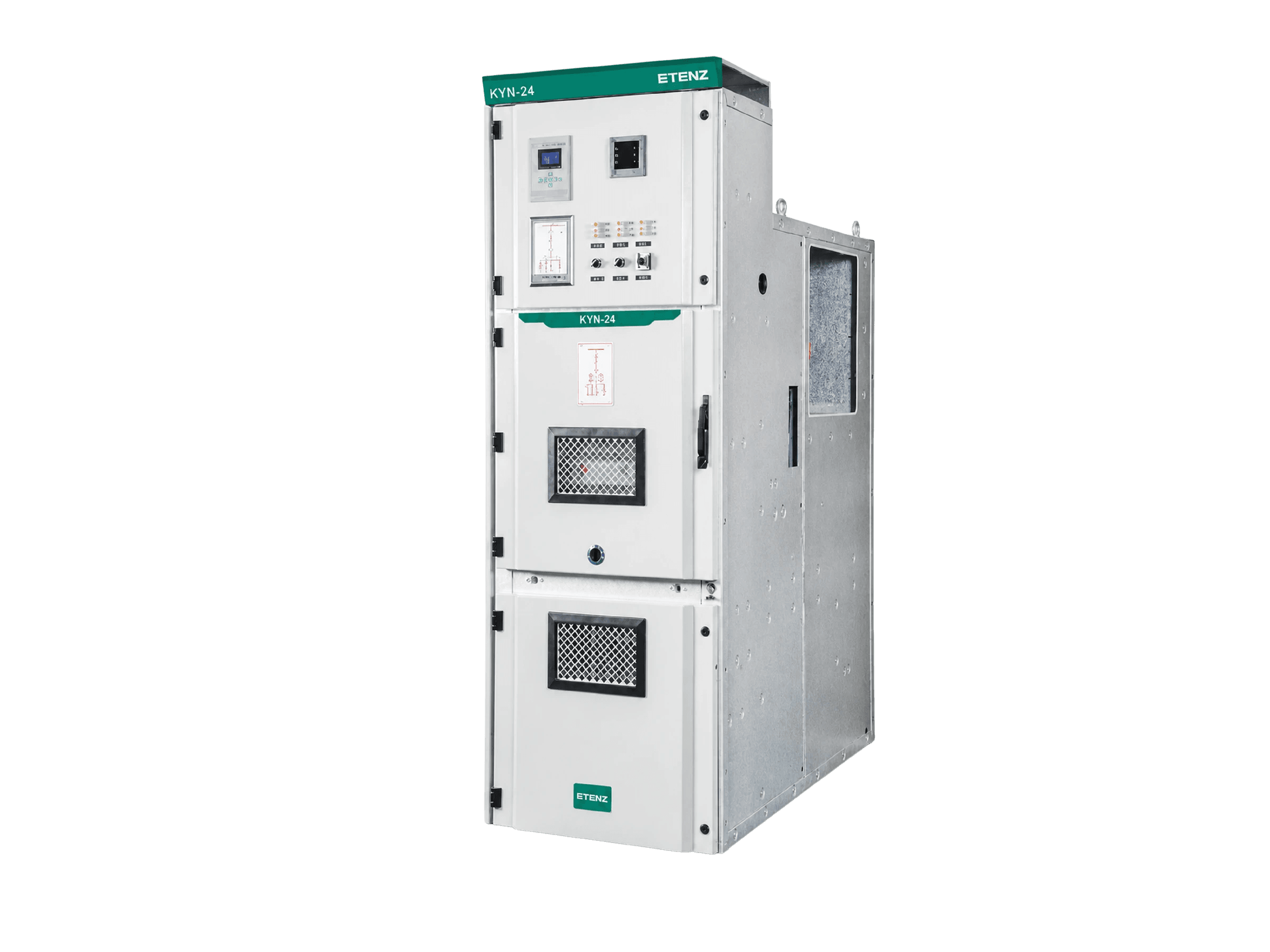
KYN□-24 Metal-Clad Withdrawable Switchgear
Distribution Switchgear